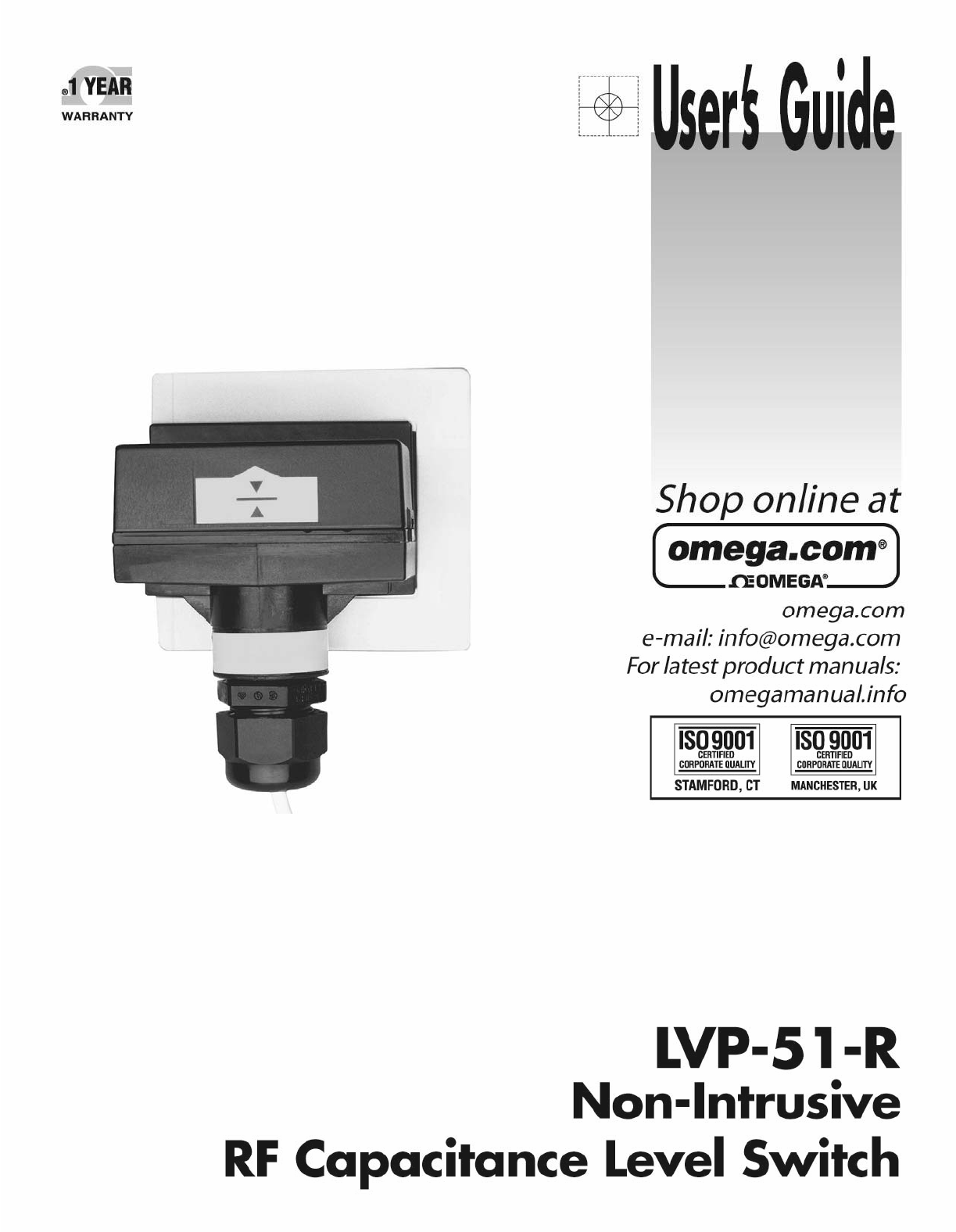
Omega-vehicle-security LVP-51 Series Manuel d'utilisateur
Naviguer en ligne ou télécharger Manuel d'utilisateur pour Accessoires pour ordinateurs Omega-vehicle-security LVP-51 Series. Omega Vehicle Security LVP-51 Series User Manual Manuel d'utilisatio
- Page / 16
- Table des matières
- MARQUE LIVRES
Résumé du contenu
1
10WIRING StepSixWiringtoaOMEGAENGINEERINGControllerLVCN‐120SeriesController(4or20mAoutput):LVCN‐120ShownSwitching Inductive Lo
11WIRING(continued) StepSixWiring the Relay Output:The LVP‐51‐R requires 12‐36 VDC power to operate the sensor and switch t
12WIRING(continued) StepSixWiring as a P‐Channel or N‐Channel output:The LVP‐51‐R can besubstituted for eitheraP‐Channel(PNP,so
13CALIBRATION StepSevenAfteritisinstalledinplace,themustbecalibratedbytheuserbeforeoperation.Everythingneededfortheprocedu
14MAINTENANCE StepSevenChecking the Point of Actuation:Raise the fluid level to the pointwhere the sensor sends a “wet” signal
15
16
2
3INTRODUCTION StepOneAboutNon‐IntrusiveRFCapacitanceTechnology:OMEGAENGINEERING'sLVP‐51‐Rlevelswitchgeneratesa highradiofre
4SPECIFICATIONS&DIMENSIONS StepTwoSpecifications:Tankmounting: Non‐intrusiveTankmat.comp.: Non‐metallicTankwallthick.: <1&
5SAFETYPRECAUTION StepThreeAboutManual:PLEASEREADTHEENTIREMANUALPRIORTOINSTALLINGORUSINGTHISPRODUCT.Thismanual includes info
6SAFETYPRECAUTION(capacitance) StepThreeMakeaFail‐SafeSystem:Designafail‐safesystemthataccommodatesthepossibilityofswitchand/orp
7INSTALLATION StepFourOMEGAENGINEERING'sLVP‐51‐RlevelswitchmaybeinstalledanywhereonatankwallusingthePE(LVP‐91)orPP(LVP
8ELECTRICAL StepFiveSupplyVoltage:ThesupplyvoltagetotheLVP‐51‐Rlevelswitchshouldneverexceedamaximumof36VDC.OMEGA ENGINEERING
9ELECTRICAL(continued) StepFiveSignalOutput(Relayswitching):Allowsthesensortoswitchasmallloadonoroffdirectly,usinganinterna
Produits connexes et manuels pour Accessoires pour ordinateurs Omega-vehicle-security LVP-51 Series
 (22 pages)
© 2020, manymanuals.fr. Tous droits réservés | 1.200 s |
 Manymanuals.com
 Manymanuals.de
 Manymanuals.fr
 Manymanuals.it
 Manymanuals.pl
 Manymanuals.cz
 Manymanuals.es
 Manymanuals-pt.com
Commentaires sur ces manuels