Omega-vehicle-security OMEGAFLEX FPU500 Manuel d'utilisateur
Naviguer en ligne ou télécharger Manuel d'utilisateur pour Radiateurs Omega-vehicle-security OMEGAFLEX FPU500. Omega Vehicle Security OMEGAFLEX FPU500 User Manual Manuel d'utilisatio
- Page / 52
- Table des matières
- DEPANNAGE
- MARQUE LIVRES
- User’s Guide 1
- Unpacking Instructions 3
- Peristaltic Pump 4
- Introduction 7
- 2.2 Left Side of the Pump 10
- 2.3 Right Side of the Pump 11
- Parts of the Pump 12
- Setting Up the Pump(s) 13
- 3.3 Attaching the Pump 14
- Tubing Information 22
- Operating the Pump 24
- 5.2 Loading the Tubing 25
- 5.3 Operating the Pump 27
- (Clamp Screw) 28
- MOTOR TURNING CLOCKWISE 28
- Maintenance 31
- (Part Number FPU500-RA) 32
- 16" x 1 33
- Troubleshooting Guide 35
- Technical Details 39
- Specifications 41
- (in.) Speed Tolerances) 43
- (in.) (mm) (in.) (mm) (Hours) 44
- Tubing Size 45
- Thickness Diameter Revolution 45
- Spare Parts and Accessories 47
- WARRANTY/DISCLAIMER 51
- RETURN REQUESTS/INQUIRIES 51
- M2219/0305 52
Résumé du contenu
FPU500OMEGAFLEX®Peristaltic PumpMADE INomega.com e-mail: [email protected] latest product manuals:omegamanual.infoUser’s GuideShop online at
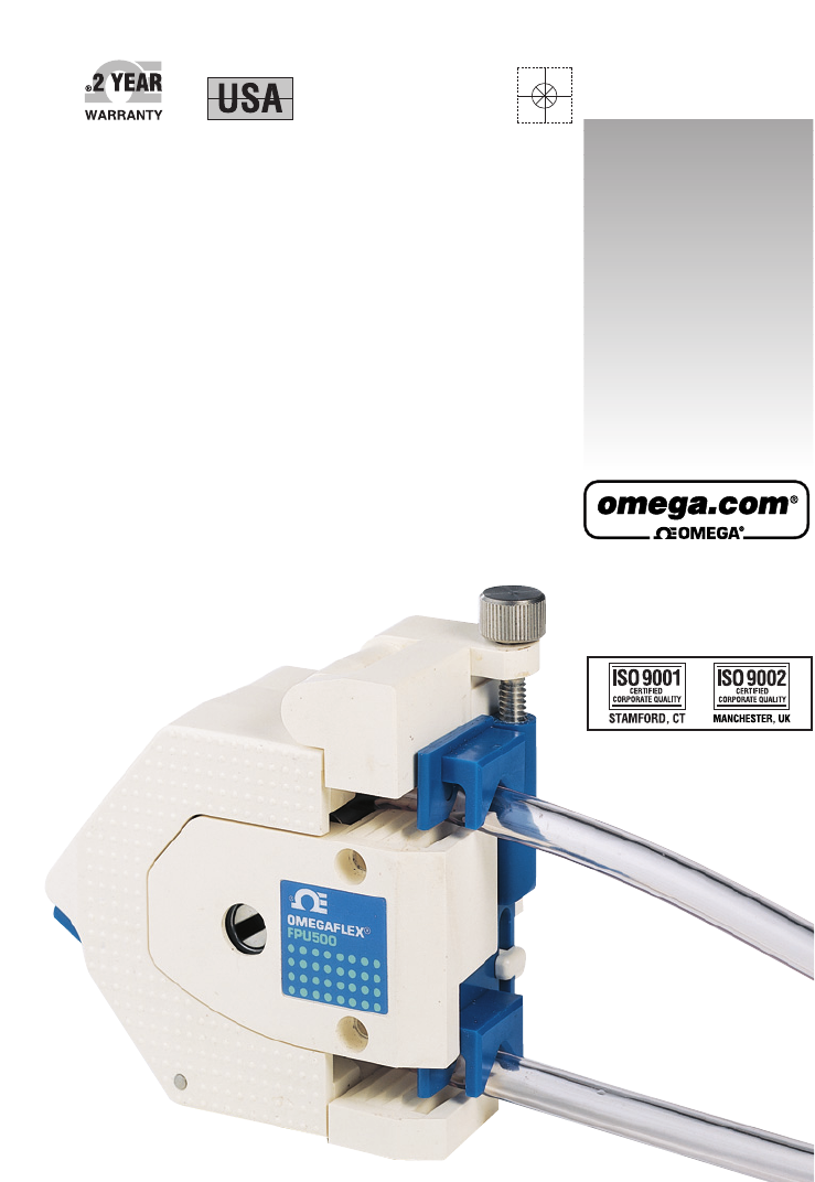
Parts of the Pump22-22.2 Left Side of the PumpFigure 2-2. View of the Left SideItem Description Function1 Stator Fixed surface for tubing compressio
Parts of the Pump22-32.3 Right Side of the PumpFigure 2-3. View of the Right SideItem Description Function3 Clamp Plate Secures the tubing during pum
Parts of the Pump22-4Notes
3Setting Up the Pump(s)3-13.1 IntroductionTo attach a single pump directly to a pump motor, follow theprocedure in Section 3.3.1.To stack two pumps t
Setting Up the Pump(s)33-23.3 Attaching the Pump3.3.1 Attaching a Single Pump Directly to the MotorRefer to Figures 3-1 through 3-4 and Figure A.Fig
Setting Up the Pump(s)33-31. Refer to Figure 3-1. Make sure the pump is in the closed position.2. Refer to Figure 3-2 and Figure A. Place the blade of
Setting Up the Pump(s)33-43.3.2 Stacking Two Pumps onto One MotorRefer to Figures 3-5 through 3-7 and Figure B.Figure 3-5. Placing the Second Pump
Setting Up the Pump(s)33-51. Refer to Figures 3-1 through 3-3. Perform Steps 1, 2 and 3 inSection 3.3.1 to put the first pump on the face of the motor
Setting Up the Pump(s)33-63.3.3 Attaching a Single Pump to an Adapter PlateRefer to Figures 3-8 through 3-11 and Figure C.Figure 3-8. Mounting the A
Setting Up the Pump(s)33-7The adapter plate is designed to have the same alignment pins andmounting holes as the front face of the standard pump motor
Servicing North America:U.S.A.: One Omega Drive, Box 4047ISO 9001 Certified Stamford, CT 06907-0047Tel: (203) 359-1660 FAX: (203) 359-7700e-mail: info
Setting Up the Pump(s)33-83.3.4 Using Your Own Adapter PlateFigure 3-12 shows the dimensions of the front of the pumpand the rear of the pump. These
Setting Up the Pump(s)33-9Notes
4Tubing Information4-14.1 Selecting TubingSelect a tubing material and size that is right for yourapplication (the fluid and flow rate that you are p
Tubing Information44-2Notes
5Operating the Pump5-15.1 IntroductionThis chapter discusses the following topics:• Loading the tubing (Section 5.2)• Operating the Pump (Section 5.3
Operating the Pump55-25.2 Loading the TubingBefore you load the tubing in the pump, make sure thatpower to the motor is turned off and that the rotor
Operating the Pump55-31. Refer to Figure 5-1 and Figure D. Snap open the Stator (1) bypushing the spring-loaded area of the Latch (2). Remove any oldt
Operating the Pump55-45.3 Operating the PumpWith the pump set up, adjust all control settings for the pumpmotor and start pumping. Figure 5-5 shows f
Operating the Pump55-5Figure 5-5b. Inlet and Outlet Flow5.4 Adjusting the Clamp ScrewOnce you start the pump, you may need to adjust the ClampScrew
1. Turn the pump motor off.2. Rotate the clamp screw a quarter turn clockwise, in order to increase the pressure of the clamp plate on the tube.3. Tur
Unpacking InstructionsiRemove the Packing List and verify that you have received all equipment, including the following (quantities in parentheses):Pe
Operating the Pump55-7Notes
6Maintenance6-16.1 Introduction• No lubrication is required for the pump. All bearingsare pre-sealed and rated for long life.• After many hours of us
Maintenance66-26.2 Replacing the Rotor Assembly(Part Number FPU500-RA)In the replacement kit you will find one Rotor Assembly (13)and two Washers (12
Maintenance66-31. Using a phillips head screwdriver, remove the two #6 Self-Tapping Screws (14) on the back of the base that hold the pumptogether.2.
Maintenance66-4Notes
7Troubleshooting Guide7-1Problem SolutionNo flow out of the outlet tubing 1. Check to see that the Stator issnapped shut. If it is, push down onthe St
Troubleshooting Guide77-2Problem SolutionFluid flows in the opposite 1. Check tubing connections to sourcedirection of what is intended and drain cont
Troubleshooting Guide77-3Problem SolutionMotor will not turn 1. Make sure the tubing is loadedproperly. The tubing should becentered in the middle of
Troubleshooting Guide77-4Notes
8Technical Details8-18.1 Theory of OperationA peristaltic pump is a fluid pump which operates to create amoving region of compression along a flexibl
iiTABLE OFCONTENTSPeristaltic PumpPageUnpacking Instructions ... iChapter 1 Introducti
Technical Details88-2Because of the back tab and groove found in the Rotor Shaftdesign, pumps can be stacked one of top of another andattached to a co
9Specifications9-1Table 9-1. Tubing Size vs Min. Motor Speed Required for Priming *Tubing Size - ID Minimum Motor Speed (RPM)1⁄32" 3001⁄16"
Specifications99-2Pump Dimensions (H x W x D): 4" x 4" x 21⁄4" (102 x 102 x 57 mm)Pump Weight: 0.9 lb (0.4 kg)Adapter Plate Dimensions
Specifications99-3Table 9-2. Average Flow Rates (Cont’d)Tubing Wall Tubing Size mL per Minimum Flow Maximum Flow Thickness Inner Diameter Revolution
Specifications99-4Tubing operating life test were done at 600 RPM, with 20°C water, 0 PSI, back pressure until the tubing breaks. Average tubing lifeh
Specifications99-5Table 9-4. Average Tubing Life (Cont'd)1⁄16 1.51⁄16 1.5 Vinyl 601⁄16 1.51⁄8 3.0 Vinyl 601⁄16 1.53⁄16 4.5 Vinyl 601⁄16 1.51⁄4 6
Specifications99-6Notes
10Spare Parts and Accessories10-1Table 10-1. Spare PartsPart Number DescriptionFPU500-SMS Standard Length Mounting ScrewsFPU500-LMS Long Mounting Scr
Spare Parts and Accessories1010-2Table 10-2. Accessories (cont’d)Part Number * Tubing Type Size Durometer(OD x ID) (Shore Hardness)RECOMMENDED TUBING
Spare Parts and Accessories1010-3You can use an optional Peristaltic Pump Motor (Part NumberFPU5-MT) to run the pumps. Figure 10-1 shows the motor. Yo
IIndexIAAdapter Plate ... 3-6Adapter Plate Specifications ... 3
Spare Parts and Accessories1010-4Notes
WARRANTY/DISCLAIMEROMEGA ENGINEERING, INC. warrants this unit to be free of defects in materials andworkmanship for a period of 25 months from date of
M2219/0305Where Do I Find Everything I Need for Process Measurement and Control? OMEGA…Of Course!Shop online at omega.comTEMPERATURE䡺⻬Thermocouple, RT
IndexIINotesI
1Introduction1-11.1 DescriptionThe peristaltic pump offers exceptional simplicity, ease-of-use, and variable flow capacity. The pump is self-priminga
Introduction11-2Notes
2Parts of the Pump2-12.1 Overall View of the PumpFigure 2-1. Overall ViewItem Description Function1 Stator Fixed surface for tubing compression2 Lat
Produits connexes et manuels pour Radiateurs Omega-vehicle-security OMEGAFLEX FPU500
 (12 pages)
© 2020, manymanuals.fr. Tous droits réservés | 1.337 s |
 Manymanuals.com
 Manymanuals.de
 Manymanuals.fr
 Manymanuals.it
 Manymanuals.pl
 Manymanuals.cz
 Manymanuals.es
 Manymanuals-pt.com
Commentaires sur ces manuels